

 English
 中文简体
 русский
 Français
 Español
 Deutsch

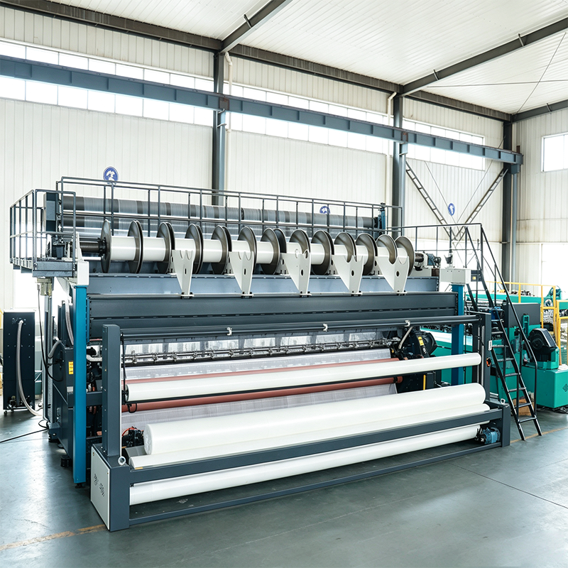
YRS3-M-G Raschel Mesh-Geogrid Biaxial Warp Knitting Machine: Engineering High-Strength Reinforcement Grids
2026-11-04
Content
- 1 Product Overview
- 2 Why Biaxial Geogrid Construction Matters
- 3 Main Technical Specifications
- 4 Engineering Features That Improve Product Quality
- 5 Advantages Compared with Less Specialized Equipment
- 6 Materials and Process Compatibility
- 7 Grid Geometry and Product Development
- 8 Manufacturing Strengths and Quality Management
- 9 Installation and Line Integration
- 10 Operation and Process Optimization
- 11 Quality Control for Finished Geogrid
- 12 Maintenance and Spare Parts
- 13 Training and Technical Service
- 14 Applications of the Finished Geogrid
- 15 Position Within a Broader Technical Textile Equipment Range
- 16 How to Select the Correct Configuration
- 17 Commercial and Production Planning Benefits
- 18 Environmental and Durability Considerations
- 19 Frequently Asked Questions
- 19.1 What is the YRS3-M-G used to produce?
- 19.2 Which fibers can be processed?
- 19.3 What does 2 warp × 2 weft mean?
- 19.4 What is the maximum working width?
- 19.5 Is the maximum speed always 1500 r/min?
- 19.6 How should the daily output figure be understood?
- 19.7 Can the machine be customized?
- 19.8 Can glass fiber and polyester be run on the same machine?
- 19.9 What information is needed for a quotation?
- 19.10 How is fabric quality checked before delivery?
- 19.11 What installation support is available?
- 19.12 What maintenance is most important?
- 19.13 Can the machine be integrated with downstream equipment?
- 19.14 Which applications use the finished geogrid?
- 20 Conclusion
- 21 References
- 22 Product: YRS3-M-G Raschel Mesh-Geogrid Biaxial Warp Knitting Machine
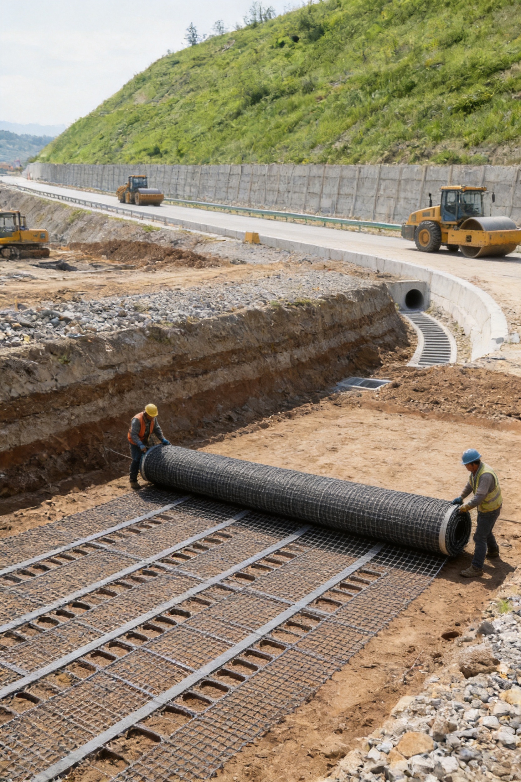
The YRS3-M-G Raschel Mesh-Geogrid Biaxial Warp Knitting Machine is designed for manufacturers producing high-strength geogrids and reinforcement meshes from glass fiber and polyester. It creates a stable biaxial structure by arranging continuous fiber bundles in both warp and weft directions and securely binding them at their intersections. This production method keeps the reinforcement bundles as straight as possible, reducing unnecessary bending and helping the finished grid use the inherent strength of the fibers efficiently.
Geogrids are used in demanding civil engineering applications where consistent tensile performance, low creep and dimensional stability are essential. Typical applications include steep slope protection, soft soil foundation treatment, reinforced soil retaining walls, embankment stabilization and other projects requiring improved load distribution. For these applications, the quality of the grid depends not only on the fiber itself, but also on the accuracy of the machine that controls fiber placement, tension, spacing, intersection binding and take-up.
The YRS3-M-G addresses these requirements through a dedicated biaxial raschel structure, a wide operating range and a configuration approach based on the intended fabric. Its nominal working width is 247 inches, its operating speed range is 20–1500 revolutions per minute, and its reference daily output is 15,000 square meters. Actual production depends on fiber type, bundle size, aperture dimensions, grid density, process settings and the required quality standard.
Product Overview
A geogrid must transfer loads in two principal directions. The warp system carries longitudinal loads, while the weft system contributes transverse reinforcement. At the intersections, the two systems must remain accurately positioned and securely bound. If the bundles shift, bend excessively or become unevenly tensioned, the final grid may show inconsistent apertures, reduced tensile efficiency and unstable dimensions.
The YRS3-M-G is developed specifically for this type of structure. Its operating principle is based on laying high-strength fiber bundles into a defined warp-and-weft arrangement and locking those bundles together with a binding system. The resulting open grid provides continuous reinforcement paths in both directions without the pronounced crimp that is common in conventional woven constructions.
The machine is suitable for glass fiber and polyester. Glass fiber is valued for high tensile strength, dimensional stability and resistance to many environmental conditions. Polyester offers flexibility, favorable handling characteristics and useful resistance to creep when correctly selected and processed. Since the two materials differ in elongation, brittleness, package behavior and tension requirements, the machine configuration must be matched to the actual yarn or roving specification.
The core product is a biaxial mesh-geogrid. Depending on the fabric design, the machine can be configured around different warp and weft spacings, grid apertures, bundle counts and binding conditions. The equipment is therefore not treated as a one-size-fits-all machine. The proposed configuration is established from the required fabric, production target, workshop arrangement and downstream roll-handling method.
Why Biaxial Geogrid Construction Matters
Soil reinforcement systems are exposed to loads that may act in several directions. Traffic, settlement, slope movement, water pressure and changes in soil density can create complex stress conditions. A biaxial geogrid distributes tensile forces through its longitudinal and transverse reinforcement members, helping stabilize the surrounding soil structure.
The grid structure also creates mechanical interlock with soil particles. The open apertures allow aggregate or soil to pass through the grid, while the reinforcement ribs resist movement after placement and compaction. The effectiveness of this interaction depends on aperture geometry, rib strength, dimensional stability and the consistency of the finished roll.
In a conventional woven material, yarns may pass over and under one another, creating a degree of crimp. Crimp can cause the yarn to bend before it begins carrying a tensile load. A biaxial warp knitting process can reduce this effect by placing the reinforcement bundles along relatively direct paths and binding the intersections without forcing the primary bundles into a strongly undulating form.
This design provides several production and performance benefits:
- More direct load paths in the warp and weft directions.
- Efficient use of the tensile strength of glass fiber or polyester.
- Consistent grid geometry when tension and binding are correctly controlled.
- Low creep potential when suitable reinforcement materials and process conditions are used.
- Improved dimensional stability during handling, installation and service.
- Adaptability to different soil conditions and reinforcement requirements.
The YRS3-M-G is therefore intended for manufacturers that need a repeatable industrial process rather than a general-purpose knitting platform with limited control over reinforcement geometry.
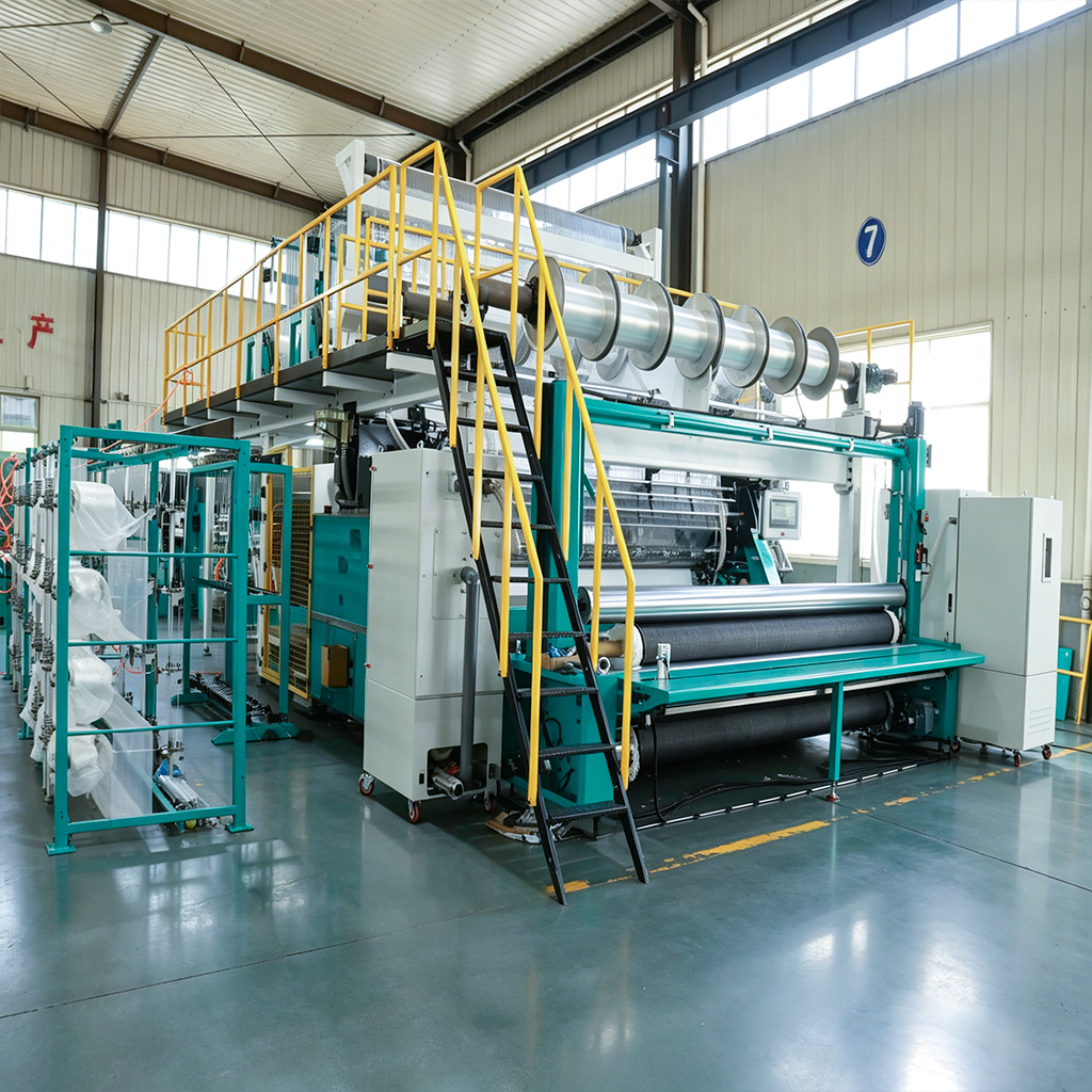
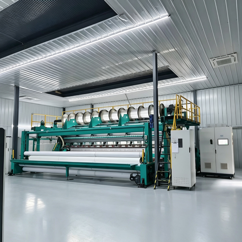
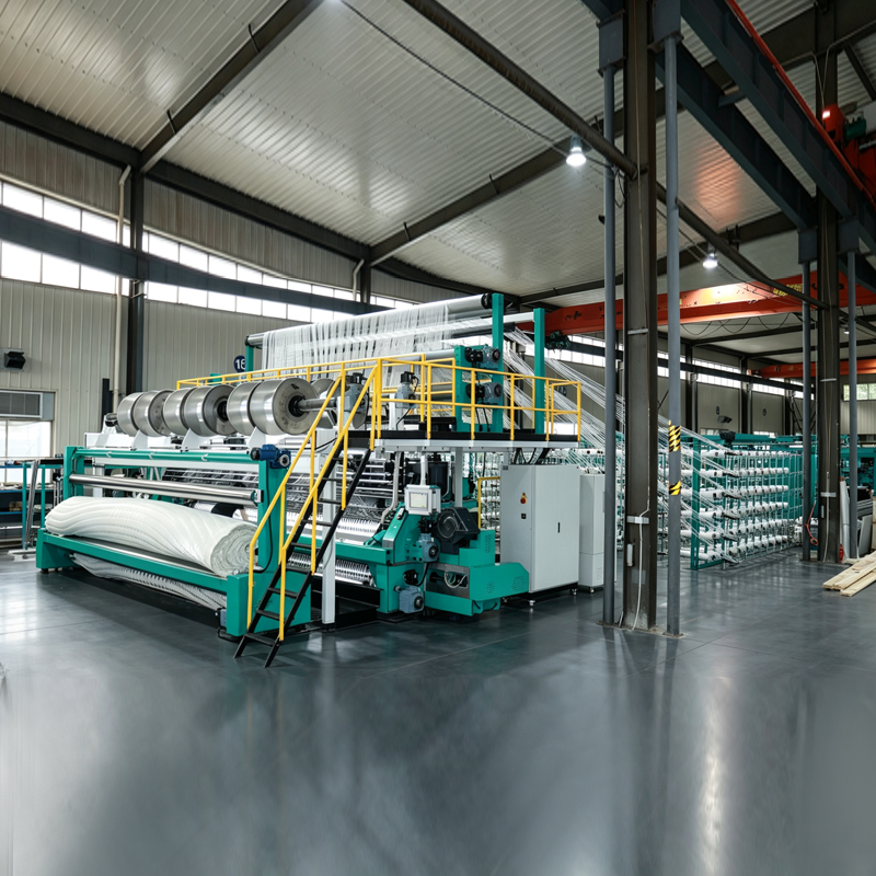
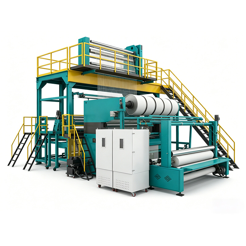
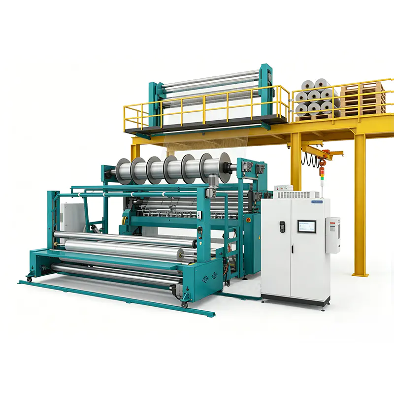
YRS3-M-G Raschel Mesh-Geogrid Biaxial Warp Knitting Machine
Main Technical Specifications
| Parameter | Specification | Production Significance |
|---|---|---|
| Machine type | Raschel mesh-geogrid biaxial warp knitting machine | Designed for open reinforcement grids with warp and weft fiber systems |
| Applicable fibers | Glass fiber and polyester | Supports common reinforcement materials for geotechnical applications |
| Machine speed | 20–1500 r/min | Provides a broad operating window for different fabric constructions |
| Working width | 247 inches | Supports wide-format production and efficient roll utilization |
| Fabric specification | 2 warp × 2 weft | Provides biaxial reinforcement in two principal directions |
| Reference daily output | 15,000 m² | Used for preliminary capacity planning; actual output varies by process |
| Core product | Mesh-geogrid and biaxial geogrid | Suitable for soil reinforcement and civil engineering applications |
The operating speed of 20–1500 r/min represents a broad available range rather than a guaranteed speed for every fabric. A heavy glass fiber construction, dense grid or large bundle may require a lower stable working point. A lighter polyester structure may operate at a higher speed if the fabric remains within the required quality tolerances.
Output must also be evaluated together with fabric width, aperture size, bundle count, yarn tension and stoppage frequency. The reference figure of 15,000 square meters per day provides a basis for early planning, but final capacity calculations should be made using the customer’s actual grid design and shift pattern.
Engineering Features That Improve Product Quality
Controlled Warp and Weft Placement
The principal function of the machine is to place reinforcement bundles accurately in two directions. Warp and weft insertion must remain synchronized so that the grid openings are uniform across the complete working width. Inconsistent placement can cause localized differences in tensile strength, irregular aperture dimensions and difficulties during coating, cutting or installation.
The YRS3-M-G is configured around the required grid pattern. The warp spacing, weft spacing and binding interval are considered together rather than as isolated parameters. This allows the manufacturer to establish a repeatable relationship between machine movement and finished fabric geometry.
Reduced Fiber Bending
Glass fiber is strong but relatively brittle. Repeated sharp bending, excessive contact pressure or uncontrolled tension changes can damage filaments and reduce the effective strength of the reinforcement bundle. Keeping the bundles as straight as possible through the grid is therefore a major advantage.
The machine layout, guide elements and tensioning arrangement are selected to provide a controlled yarn path from the creel to the binding and take-up areas. The objective is not simply to move the fiber through the machine, but to preserve its condition while maintaining the specified grid geometry.
Stable Intersection Binding
The intersections between warp and weft bundles are critical load-transfer points. They must be bound firmly enough to preserve the grid structure during production, winding, transport and installation. At the same time, the binding system must avoid unnecessary disturbance to the primary reinforcement bundles.
A stable binding action helps prevent shifting, local distortion and inconsistent aperture sizes. It also supports the production of rolls that can be unwound and installed without excessive deformation. The binding configuration is checked against the agreed fabric sample or technical drawing during commissioning and pre-delivery testing.
Wide Working Width
A working width of 247 inches allows manufacturers to produce wide reinforcement grids in a single pass. Wide-format production can reduce the number of longitudinal seams required in downstream applications and may improve material utilization in large-scale civil engineering projects.
The actual usable width depends on fabric construction, edge requirements, roll format and downstream cutting arrangements. During project planning, the working width is reviewed together with the workshop layout, operator access, take-up system and transportation route inside the plant.
Flexible Operating Range
The speed range gives production teams room to optimize the machine according to the material and fabric. A lower speed may be selected during the development of a heavy glass fiber grid or when a new binding pattern is being introduced. Once the process is stable, the working point can be increased if the fabric continues to meet tensile, dimensional and visual requirements.
This approach is more useful than operating permanently at a nominal maximum speed. The best production rate is the highest stable speed that maintains fabric quality, minimizes waste and protects the fiber path from unnecessary stress.
Advantages Compared with Less Specialized Equipment
Many textile machines can create open structures, but not all are optimized for geogrid production. A machine designed for apparel mesh, lightweight technical netting or conventional fabric may not provide the tension control, bundle handling or structural rigidity required for glass fiber reinforcement.
The YRS3-M-G offers several advantages over less specialized alternatives.
Designed Around Reinforcement Bundles
Geogrid production uses rovings, bundles or high-strength yarn packages that behave differently from ordinary textile yarns. The machine must accommodate larger linear densities, controlled tension and the need to avoid filament damage. The YRS3-M-G is developed for this reinforcement environment, allowing its creel, guide elements and insertion systems to be selected according to the material.
Better Use of Fiber Tensile Strength
The near-straight arrangement of the warp and weft bundles helps reduce the amount of fiber strength lost through unnecessary crimp. This is particularly valuable when glass fiber is used, because the material’s high tensile potential is one of the main reasons it is selected for geotechnical reinforcement.
More Consistent Biaxial Performance
A grid with uneven warp and weft placement may perform differently from one side of the roll to the other. Specialized control of the two reinforcement directions supports more consistent tensile behavior and aperture geometry. This consistency is important when the material is supplied to contractors who expect predictable installation and engineering performance.
Configuration for the Target Fabric
Generic equipment often forces a producer to adapt the product to the machine. The YRS3-M-G follows the opposite principle: the machine configuration is developed from the desired grid. The customer’s fiber, aperture, bundle spacing, roll format and target output are reviewed before the final proposal is prepared.
Integration with Downstream Handling
The take-up and batching arrangement can be considered together with downstream cutting, coating, packaging or rolling requirements. This reduces the risk of purchasing a knitting machine that produces the correct fabric but cannot be efficiently integrated into the rest of the plant.
Materials and Process Compatibility
Glass Fiber
Glass fiber is widely used when high tensile strength, dimensional stability and resistance to corrosion and oxidation are required. It can be suitable for geogrids used in slope stabilization, soil reinforcement and foundation treatment. However, glass fiber requires careful handling because filaments can be damaged by excessive friction, sharp guide transitions or unstable tension.
For glass fiber production, the yarn path should be designed to avoid abrupt direction changes. Guide surfaces must be appropriate for the material, and tension should remain sufficiently stable to prevent slack sections and sudden loading. The binding action must also secure the intersection without creating unnecessary abrasion.
Polyester
Polyester provides a different processing profile. It generally offers greater flexibility and elongation than glass fiber and may require different tension settings, package arrangements and take-up conditions. Polyester geogrids can be selected for projects where low creep, flexibility and resistance to environmental conditions are important.
The machine is configured according to the specific polyester yarn or bundle specification. Linear density, package size, elongation, finish and required grid strength all influence the correct process settings.
Fiber Package and Creel Arrangement
The creel must supply the required number of warp and weft bundles with stable tension throughout the production run. Package position, unwinding direction and yarn-path organization affect operator access and process stability. A suitable arrangement also helps reduce accidental contact between adjacent bundles.
During configuration, the fiber type, package dimensions, number of ends, target width and expected production duration are reviewed. The objective is to provide a material supply system that supports long runs without introducing avoidable tension variation.
Grid Geometry and Product Development
Grid geometry is determined by several connected variables. Warp spacing controls the distance between longitudinal reinforcement members. Weft spacing controls the transverse arrangement. The binding pattern determines how the intersections are secured and how the structure responds during handling.
A larger aperture may improve aggregate interlock in one application, while a smaller aperture may be preferred for a different soil gradation or load-transfer requirement. Bundle size and spacing must be selected together because increasing reinforcement density can change the stiffness, open area, roll weight and operating speed.
When a customer provides a fabric sample or drawing, the engineering team can use it as the basis for defining machine settings and acceptance criteria. The sample helps clarify the intended aperture, edge condition, bundle appearance, binding pattern and dimensional tolerances.
Product development normally proceeds through the following stages:
- Review the fiber type, bundle specification and package format.
- Confirm the required grid pattern, aperture and working width.
- Assess the target tensile performance and production volume.
- Define warp and weft insertion conditions and binding requirements.
- Check the workshop footprint, floor loading and utility conditions.
- Prepare a machine configuration and preliminary production estimate.
- Produce or verify a representative fabric sample.
- Use the approved sample for final testing and acceptance.
This fabric-led process reduces the risk of selecting equipment based only on a nominal speed or width figure. It connects the machine design with the actual product that the customer plans to sell.
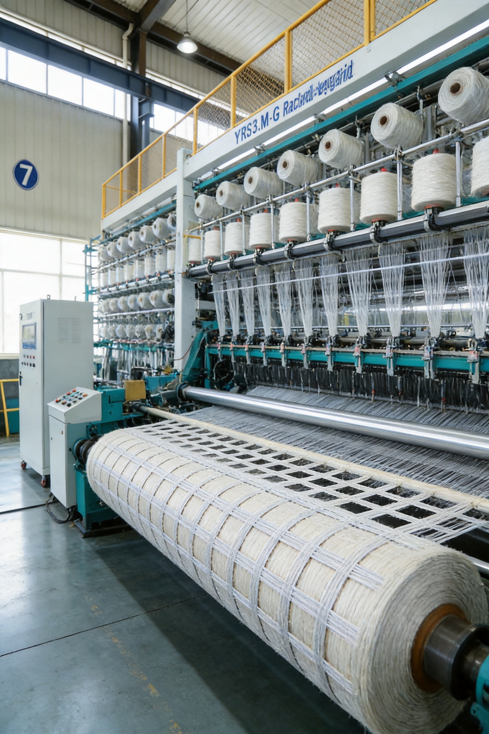
Manufacturing Strengths and Quality Management
Changzhou Yuanyang Electromechanical Technology Co., Ltd. combines research and development, manufacturing, sales and technical service in the warp knitting machinery sector. Its product range includes stitch-bonding machines, biaxial warp knitting machines, multiaxial warp knitting machines, carbon fiber multiaxial machines, powder scattering machines and web laying machines.
This range provides an engineering base for developing equipment used with difficult materials and complex technical fabrics. Geogrid production requires more than a basic knitting mechanism. It involves material handling, structural design, control integration, precision assembly, commissioning and long-term service. Experience across related machine categories helps support these connected requirements.
Research and Development
The company’s R&D team includes engineers with experience in textile machinery and technical fabric applications. Development work focuses on machine performance, structural design, special material processing and stable long-term operation.
For the YRS3-M-G, the engineering focus includes the machine frame, warp and weft insertion systems, binding bar movement, drive and control configuration, tensioning arrangement and take-up system. Each area contributes to the final fabric. A rigid frame supports alignment, controlled motion protects geometry, and a suitable take-up system helps preserve the grid after formation.
Precision Manufacturing
Production takes place through controlled stages that include component procurement, machining, assembly, testing and debugging. The manufacturing process is organized to ensure that critical components are inspected and correctly integrated before the machine enters final testing.
Accurate machining is important because small alignment errors can become visible across a wide working width. The assembly process therefore pays attention to the relationship between the frame, insertion components, guides, binding mechanisms, drive elements and take-up system.
Factory Testing
Every machine is tested before delivery. Testing includes the operation of the main drive, warp and weft systems, binding action, control functions and take-up arrangement. For a geogrid machine, the test process also includes verification of grid geometry against the agreed fabric reference whenever a customer sample or drawing is available.
Factory testing gives the customer an opportunity to confirm that the machine has been assembled and debugged before shipment. It also enables engineers to identify issues under controlled conditions rather than during the initial installation at the customer’s plant.
Intelligent Warehouse and Component Management
The manufacturing base in Danyang is supported by an intelligent warehouse that manages receiving, storage, sorting and dispatch. Organized component management helps reduce search time, improve traceability and support efficient production scheduling.
For machinery projects involving many mechanical, electrical and control components, correct storage and timely availability are important. A controlled warehouse process contributes to more reliable assembly and helps reduce the risk of missing or incorrectly identified parts.
Customization Capability
Technical textile producers often require non-standard configurations. Their fibers may have unusual package dimensions, their fabric may require a specialized binding pattern, or their workshop may impose restrictions on machine length and access. Yuanyang’s manufacturing and engineering capabilities support modifications related to machine structure, process modules, layout and special materials.
Customization can include functional module development, adaptation for difficult-to-process materials, structure and layout redesign, and process-oriented optimization. The purpose is not customization for its own sake, but to ensure that the equipment remains practical for the customer’s fabric, facility and production plan.
Installation and Line Integration
Installation begins with a review of the workshop and the intended production line. Floor loading, machine footprint, operator access, electrical supply, material flow and downstream handling should be confirmed before delivery.
On arrival, installation normally covers levelling and anchoring, connection of the electrical supply, assembly of relevant machine sections, checking of the warp and weft systems, adjustment of the binding action and commissioning of the take-up unit.
The machine can be integrated with downstream cutting, batching, coating, inspection or packaging equipment. The take-up and roll format should be selected according to the customer’s handling requirements. A large roll may improve efficiency in some projects, while a smaller roll may be preferable where installation teams need easier manual handling.
Operator access and guarding are reviewed as part of the installation plan. Clear access supports material replacement, inspection and maintenance. Appropriate guarding protects personnel from moving components while allowing necessary production checks.
Utilities and Workshop Requirements
Electrical requirements and control interfaces are agreed during configuration. The workshop should provide adequate space for material loading, operator movement, roll removal and maintenance activities. Floor conditions must be suitable for the machine’s weight and operating loads.
The machine layout should also account for the path from fiber storage to the creel, from the creel to the knitting zone, and from the take-up unit to inspection or packaging. Efficient material flow reduces unnecessary handling and helps maintain a clean and organized production environment.
Operation and Process Optimization
Successful operation begins with correct material preparation. Fiber packages should be identified, inspected and loaded according to the production plan. Damaged packages, contaminated fiber or inconsistent package tension can affect grid appearance and machine stability.
During start-up, operators should confirm the threading route, guide condition, tension settings, binding components and take-up parameters. The first section of fabric should be inspected for aperture size, alignment, binding consistency, edge quality and visible fiber damage.
Once the structure is stable, the operator can gradually adjust the speed toward the required working point. Changes should be made carefully because speed, tension, insertion timing and take-up behavior influence each other. A higher speed is not beneficial if it causes frequent stops, broken fibers, unstable apertures or excessive waste.
Important process indicators include:
- Warp and weft tension stability.
- Uniformity of grid apertures across the working width.
- Consistency of intersection binding.
- Presence of broken filaments or damaged bundles.
- Edge straightness and roll alignment.
- Take-up hardness and roll formation.
- Machine vibration, unusual noise or temperature changes.
- Production output and stoppage frequency.
Recording these indicators helps the production team establish a repeatable process. It also provides useful information when changing from glass fiber to polyester or when introducing a new grid pattern.
Quality Control for Finished Geogrid
Finished geogrid quality should be assessed through both visual inspection and measurable technical checks. The inspection plan depends on the customer’s specification and intended application, but normally includes dimensional and structural observations.
Visual inspection can identify broken bundles, loose intersections, irregular apertures, edge damage, contamination and roll telescoping. Dimensional checks can confirm working width, aperture size, bundle spacing and roll length.
Mechanical testing may be used to evaluate tensile strength, elongation, junction performance and other properties required by the application. Where the geogrid will be used for soil reinforcement, the test program should be aligned with the relevant project specification or purchasing standard.
The machine itself contributes to quality by maintaining a stable and repeatable process. However, quality also depends on fiber selection, operator training, preventive maintenance, environmental conditions and the consistency of incoming materials.
Pre-Delivery Verification
Before shipment, the machine is tested in the factory. The agreed fabric sample or drawing can be used as the reference for checking the grid geometry. Engineers review whether the warp and weft systems operate correctly, whether the binding action is stable and whether the take-up forms an acceptable roll.
Pre-delivery verification may also include control-system checks, safety-function checks, drive testing and inspection of accessible mechanical components. Documentation and operating guidance are prepared to support installation and commissioning at the customer’s site.
Maintenance and Spare Parts
Preventive maintenance is essential for keeping the grid geometry stable. The yarn path, guide elements, binding area, drive components and take-up system should be inspected at defined intervals.
Guide elements must be checked for wear, roughness, contamination or damage. Even a small surface defect can affect glass fiber and increase the risk of filament breakage. Tension calibration should be reviewed when the material, package or production construction changes.
Lubrication should follow the machine’s maintenance schedule and use suitable lubricants in the specified locations. Excess lubricant must be prevented from reaching the fabric. Drive systems, bearings, fasteners and moving mechanisms should be inspected for unusual vibration, noise or heat.
A practical maintenance plan can include the following activities:
| Frequency | Typical Activity | Purpose |
|---|---|---|
| Each shift | Check fiber path, binding area, fabric appearance and abnormal sounds | Detect early signs of damage or instability |
| Daily | Clean accessible guides and inspect take-up alignment | Maintain smooth material movement and roll formation |
| Weekly | Review tension settings, fasteners and moving components | Prevent gradual changes in grid geometry |
| Monthly | Inspect drive elements, bearings and lubrication points | Support reliable long-term operation |
| Scheduled shutdown | Calibrate, replace worn parts and review machine alignment | Restore process accuracy and reduce unplanned downtime |
Common spare parts should be planned according to production intensity, material type and local service conditions. Keeping suitable guides, wear components, sensors and other critical parts available can shorten recovery time after an unexpected failure.
Training and Technical Service
Installation is only the beginning of successful machine operation. Operators must understand material loading, threading, tension adjustment, speed selection, fabric inspection and safe access. Maintenance personnel need additional instruction in lubrication, alignment, troubleshooting and replacement of wear parts.
Yuanyang provides on-site installation, commissioning and training until the equipment reaches the agreed operating condition. Training can include practical instruction for knitters and maintainers, production parameter management, quality control and workshop planning.
Workshop management training may cover production scheduling, process records, quality documentation, preventive maintenance and response procedures for fabric defects. This broader support is valuable when a customer is establishing a new geogrid production line rather than simply adding one machine to an existing operation.
After-sales engineers assist with production issues and troubleshooting. Remote communication can often identify whether a problem relates to material preparation, tension, binding, take-up, control settings or mechanical wear. When on-site support is required, service planning can be based on the information collected by the production team.
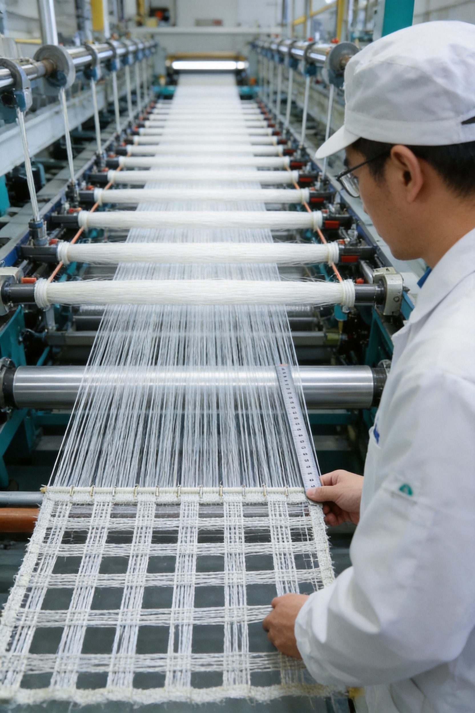
Applications of the Finished Geogrid
Steep Slope Protection
Geogrids can reinforce soil layers on steep slopes by improving tensile resistance and helping control lateral movement. The grid works together with soil, facing systems and drainage arrangements to create a more stable structure. Consistent aperture geometry supports predictable placement and helps maintain the designed reinforcement layout.
Soft Soil Foundation Treatment
Soft soil can deform under construction and service loads. A suitable geogrid can distribute loads across a wider area and improve the interaction between fill material and the underlying foundation. Low creep and stable dimensions are especially important when long-term deformation must be controlled.
Reinforced Soil Retaining Walls
In reinforced soil retaining walls, geogrid layers extend into the backfill and connect the facing system with the retained soil mass. The reinforcement resists tensile forces and helps stabilize the wall. A strong biaxial grid may be selected when both longitudinal and transverse reinforcement behavior are required.
Embankments and Ground Improvement
Geogrids may also be used in road embankments, working platforms, foundation improvement systems and other civil engineering structures. The correct product depends on the soil, load, drainage, installation method and design standard. The machine’s role is to provide a stable and repeatable grid from the selected reinforcement fiber.
Position Within a Broader Technical Textile Equipment Range
The YRS3-M-G is part of a broader range of machines for fiberglass and technical textile production. Different reinforcement products require different structures, materials and process modules, so the equipment should be selected according to the fabric rather than by machine name alone.
| Machine Type | Typical Fabric | Typical Application Direction |
|---|---|---|
| YRS3-M-G | Mesh-geogrid and biaxial grid | Geotechnical reinforcement, slopes and foundations |
| High-strength biaxial warp knitting machine | Dense biaxial reinforcement fabric | Structures requiring higher bundle density |
| Biaxial machine with nonwoven fabric | Grid combined with a nonwoven layer | Reinforcement with filtration or drainage functions |
| Chopped fiber biaxial warp knitting machine | Grid with chopped fiber coverage | Composite mats and products requiring additional in-plane coverage |
| Multiaxial warp knitting machine | Multidirectional reinforcement fabric | Composite preforms with diagonal fiber orientations |
This product range gives customers access to related technologies when their business develops beyond standard biaxial geogrid. It also reflects the company’s experience with glass fiber, carbon fiber, polyester, nonwoven layers, chopped fiber and complex reinforcement structures.
How to Select the Correct Configuration
Before requesting a quotation, the customer should prepare as much information as possible about the intended product. This allows the engineering team to evaluate the correct machine structure and avoid relying on incomplete assumptions.
- Fiber type, linear density and package specification.
- Required warp and weft bundle count.
- Target aperture size and grid spacing.
- Finished width and edge requirements.
- Required roll diameter, roll length or roll weight.
- Expected daily output and operating shifts.
- Applicable tensile and dimensional requirements.
- Workshop dimensions, floor conditions and utility availability.
- Downstream cutting, coating, inspection or packaging equipment.
- Fabric sample, technical drawing or project specification.
Providing a sample or drawing is particularly useful. It gives the machine builder a practical reference for the grid appearance, aperture, binding and edge condition. If the customer is developing a new geogrid, the engineering discussion can instead begin with the required soil application, fiber performance and target production capacity.
Commercial and Production Planning Benefits
Purchasing a specialized machine should be evaluated over the complete production life cycle. A low initial price may not represent the lowest total cost if the machine causes high waste, frequent stoppages, difficult maintenance or inconsistent fabric quality.
The YRS3-M-G is intended to support production stability through a configuration based on the customer’s actual product. Better control of fiber placement can reduce material waste caused by irregular apertures or broken bundles. A suitable take-up arrangement can reduce roll-handling problems. A maintenance and training program can improve operator response and reduce avoidable downtime.
The wide working width can also support efficient production for large projects. When the machine is integrated with an appropriate downstream line, the manufacturer may reduce manual handling and improve consistency from knitting through packaging.
Capacity planning should remain realistic. The reference output of 15,000 square meters per day is not a universal guarantee. A responsible production estimate must consider the fabric design, speed, shift length, setup time, material changes, inspection, maintenance and expected stoppages.
Environmental and Durability Considerations
Geogrids are selected for infrastructure projects where service life and environmental resistance are important. Glass fiber and polyester offer different combinations of strength, dimensional stability, chemical resistance and creep behavior. The final product must be selected according to the soil, moisture, temperature, installation method and project design.
The machine supports this objective by helping maintain the intended reinforcement geometry. A grid with stable spacing and secure intersections is more likely to perform consistently than one with uncontrolled variation. However, the machine does not replace correct material selection or engineering design. The fabric, coating if used, soil and installation conditions must be evaluated together.
Efficient production can also reduce material waste. Stable tension, accurate binding and controlled take-up help limit defective sections. Preventive maintenance further supports resource efficiency by extending component life and reducing emergency replacement.
Frequently Asked Questions
What is the YRS3-M-G used to produce?
The machine is used to produce biaxial mesh-geogrids and reinforcement grids. It arranges high-strength fiber bundles in warp and weft directions and binds them at their intersections to form an open, stable grid structure.
Which fibers can be processed?
The standard applicable fibers are glass fiber and polyester. The creel, guide elements, tensioning arrangement and process settings should be selected according to the actual fiber specification because glass fiber and polyester have different handling characteristics.
What does 2 warp × 2 weft mean?
The specification describes the biaxial reinforcement architecture. Two warp systems and two weft systems are used to form the grid, providing reinforcement in both principal directions. The exact bundle spacing and aperture depend on the configured fabric design.
What is the maximum working width?
The stated working width is 247 inches. The effective production width may depend on edge requirements, fabric construction, roll format and the customer’s downstream process.
Is the maximum speed always 1500 r/min?
The machine speed range is 20–1500 r/min. The best production speed depends on fiber type, bundle size, grid density, aperture, binding pattern and quality requirements. A lower speed may be more suitable for heavy glass fiber structures, while lighter constructions may operate at a higher stable speed.
How should the daily output figure be understood?
The reference daily output is 15,000 square meters. It is intended for preliminary planning only. Actual output depends on fabric construction, process parameters, operating shifts, setup time, maintenance and stoppages.
Can the machine be customized?
Yes. Configuration can be developed around the fiber, grid pattern, working width, roll format, target output and workshop requirements. Possible adaptations include machine layout, creel and tensioning arrangement, drive and control interfaces, binding conditions and take-up format.
Can glass fiber and polyester be run on the same machine?
The machine can be configured for both materials, but changing between them may require appropriate adjustments to tension, package arrangement, guides, process settings and fabric parameters. The exact changeover procedure depends on the fiber specifications and product designs.
What information is needed for a quotation?
The most useful information includes fiber type, yarn or roving specification, grid pattern, aperture, required width, target output, roll format, workshop details and a fabric sample or drawing. These inputs allow the proposed machine configuration and expected working point to be evaluated more accurately.
How is fabric quality checked before delivery?
The machine is tested before shipment. Engineers operate the warp and weft systems, inspect the binding action, check the control functions and evaluate the take-up arrangement. When a customer sample or drawing is available, the produced grid can be compared with that reference.
What installation support is available?
Support includes installation, levelling, anchoring, electrical connection guidance, commissioning and operator training. Engineers can also assist with the initial fabric setup and adjustment until the equipment reaches the agreed operating condition.
What maintenance is most important?
Regular inspection of guides, yarn paths, tensioning components, binding elements, lubrication points, drive systems and take-up components is essential. Glass fiber production requires particular attention to guide-surface condition because rough or damaged surfaces may increase filament breakage.
Can the machine be integrated with downstream equipment?
Yes. The take-up and batching arrangement can be selected according to downstream cutting, coating, inspection, packaging or rolling requirements. Electrical and control interfaces should be agreed during the configuration stage.
Which applications use the finished geogrid?
Typical applications include steep slope protection, soft soil foundation treatment, reinforced soil retaining walls, embankments, road foundations and other projects requiring improved load distribution and restraint of lateral soil movement.
Conclusion
The YRS3-M-G Raschel Mesh-Geogrid Biaxial Warp Knitting Machine provides a dedicated production solution for manufacturers of high-strength biaxial geogrids. Its design focuses on the requirements that distinguish reinforcement grids from ordinary textile mesh: accurate warp and weft placement, stable intersection binding, controlled fiber tension, reduced bundle bending and consistent take-up.
With a 247-inch working width, a 20–1500 r/min speed range, a 2 warp × 2 weft configuration and a reference daily output of 15,000 square meters, the machine offers a broad platform for glass fiber and polyester geogrid production. The actual working point is established from the customer’s fabric, allowing the process to be optimized for grid density, aperture, bundle size and quality requirements.
Its main competitive advantage is the combination of specialized geogrid engineering and project-based configuration. The equipment is supported by manufacturing, testing, customization, installation, training and after-sales service capabilities. This complete approach helps customers move from a fabric concept or sample to a stable industrial production line.
For manufacturers serving civil engineering, foundation reinforcement and slope stabilization markets, the machine can provide a practical foundation for producing grids with high tensile strength, low creep, dimensional stability and resistance to demanding service conditions. The best results are achieved when the machine, fiber, fabric geometry, downstream equipment and quality standard are planned as one integrated system.
References
1. Product specification information for the YRS3-M-G Raschel Mesh-Geogrid Biaxial Warp Knitting Machine.
2. Technical information on glass fiber and polyester reinforcement materials supplied for machine configuration.
3. Internal manufacturing and quality-control procedures for warp knitting machinery production, assembly, testing and commissioning.
4. Technical project requirements for geogrids used in steep slope protection, soft soil foundation treatment and reinforced soil retaining wall systems.
5. General engineering principles for biaxial reinforcement structures, soil interlock, tensile load transfer and dimensional stability.
6. Maintenance and operator-training guidance for warp knitting equipment, fiber handling systems, binding mechanisms and take-up units.
Product: YRS3-M-G Raschel Mesh-Geogrid Biaxial Warp Knitting Machine

News
-
Three quotations land on the same desk for the same polyester nonwoven line, and on paper they look interchangeable. Each is priced per metre of working width. Each quotes a similar top speed. Each c...
READ MORE -
Two buyers open the same catalogue and both ask for a warp knitting machine. One needs a 4.5 m wide glass-fibre geogrid with 0° and 90° yarns stitched together for a soil-reinforcement contract; the ...
READ MORE -
Two quotations land on the same desk. Both offer a multiaxial warp knitting line, both list the same working width, both promise high output. One buyer signs and discovers six months later that the f...
READ MORE -
A fabric engineer compares two swatches on a cutting table. One is a lightweight mesh that holds its shape, resists runs, and stretches very little. The other is a soft jersey that curls at the edges...
READ MORE
-
Contact Info.
+86-198 5534 1617
+86-134 0158 3002yuanyang@yywarpknitting.com 699#, Shengzhi West Rd, Lvcheng Town, Danyang City, Zhenjiang City, Jiangsu Province, China

-
QR Code
-
Quick Links
Home About Products Manufacturing Customization News Contact -
Product List
Machine for Chemical Fiber Textile Machine for Fiberglass Textile Machine for Carbon Fiber Textile -
About Us
Company Profile Factory Gallery Value-added Service
Copyright © 2026 Changzhou Yuanyang Electromechanical Technology Co., Ltd. All Rights Reserved.
Custom Warp Knitting Machine Manufacturers
